The end of the arm aims it
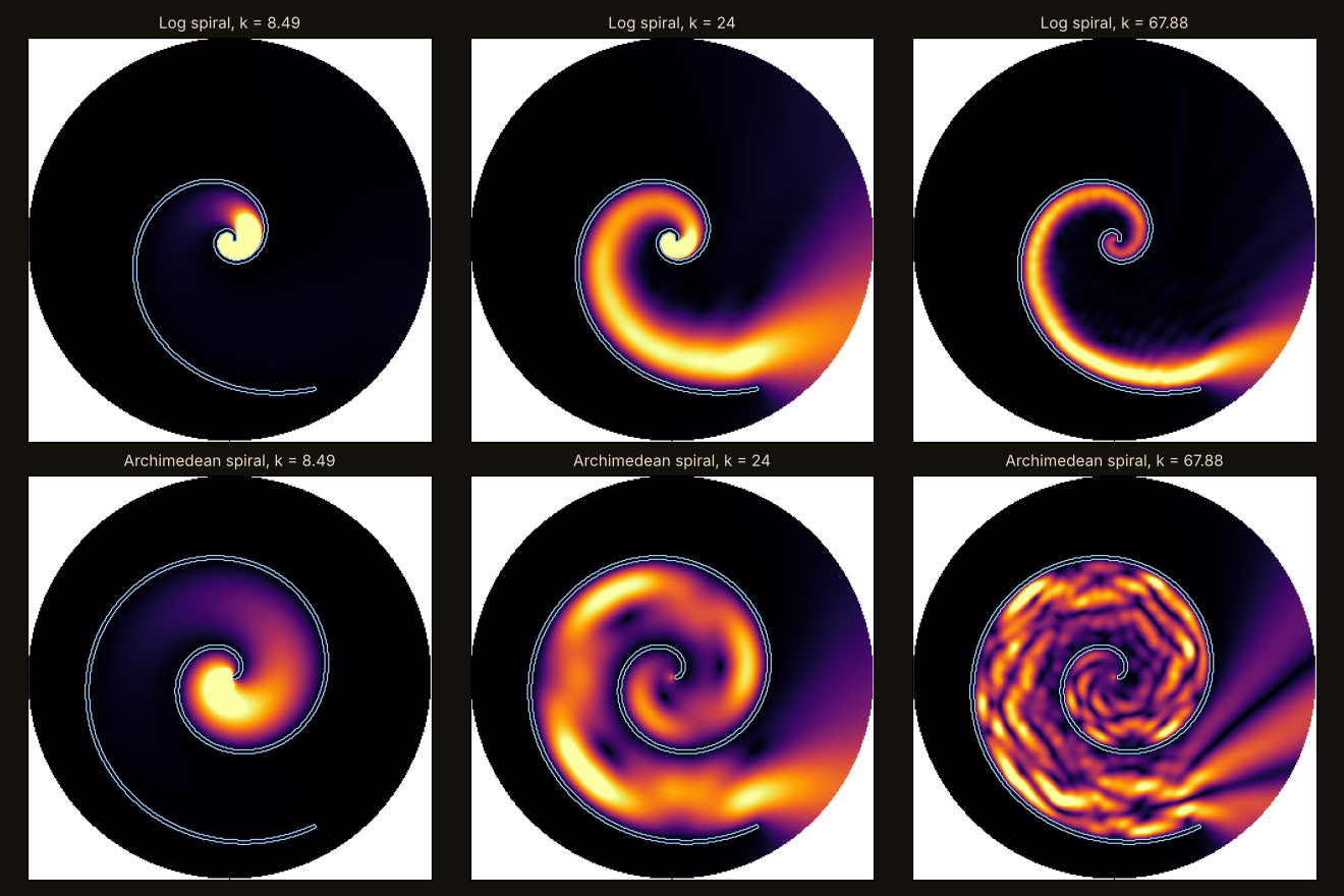
A log-spiral antenna is said to work the same at every frequency, because its shape looks the same at every scale. We fed sound into the centre of a log spiral in a 2-D wave model. The beam does stay steady over more than four octaves, steadier than from a spiral of constant width. But the sound winds out along the arm and leaves through its mouth, and the end of the arm sets where the beam points.
The verdict
Real effect, different reason
In a 2-D wave model a log spiral does send sound out in a steady beam across more than four octaves, steadier than a spiral of constant width, but not by turning with frequency as the antenna principle predicts: the sound winds out along the arm and leaves through its mouth, and the end of the arm aims it.
How the verdict was set. The first, preregistered test failed to give a verdict: it asked for the beam to turn with frequency, and it did not, and the constant-width control was steadier than expected too. A second test was written down after that run, before it ran, on new shapes and with its own verdict rule. One of its two mechanism cases was built rotated by mistake; that was declared, rebuilt and re-run. All of it is on the record below.
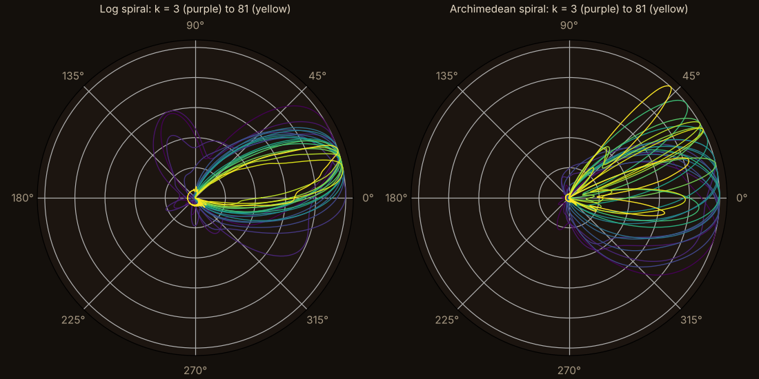
With one arm, the log spiral keeps the same beam from k = 4.2 to 81, 4.25 octaves; the constant-width spiral holds for 2.75. With two arms: 3.5 octaves against 2.25.
The antenna principle says the beam should rotate by a fixed angle per frequency step. No step matched it: scores 0.12 to 0.79 against a bar of 0.90.
Cut the arm back by 1 rad at its outer end and the beam turns by 0.89, 0.97 and 1.11 rad at three frequencies. Cut 1 rad from the inner start instead and it turns by 0.00, 0.00 and −0.05.
Antenna lore. A log-spiral antenna works the same at every frequency (Rumsey, IRE National Convention Record 1957; Dyson, IRE Trans. Antennas Propag. 1959). No show is cited for it in the lab’s registry.
The reason given is scale symmetry: scaling a log spiral is the same as rotating it, so a change of frequency should only rotate the pattern. The episode tests the steadiness and the reason separately.
Preregistered in PREREG.md (commit 16d9dd0) before any code; Addendum 1 (61a5a90) before run 2; Addendum 2 (35c4cf2) before run 2b. Self-graded, with no outside review. Lab files are listed at the foot of the page.
The setup
A rigid spiral wall in a 2-D box with absorbing edges, sound fed in at the centre, and the far-field pattern read at 20 wavenumbers from k = 3 to 81, a quarter octave apart. The comparison is an Archimedean spiral, whose channel keeps the same width all the way out.
A band counts as steady while each pattern matches the one at k = 12 with a correlation of at least 0.80. Run 2 used two new pairs of shapes (one arm, wound more tightly to 2.75 turns; two arms) and two mechanism cases: the arm cut back at its outer end, and cut back at its inner start.
The checks
Run 1 was written down before any code. Run 2 was written down after run 1 and before it ran.
| Check | Result | Numbers |
|---|---|---|
| The wave engine’s own tests and planted bugs | pass | 15 passed; 8 of 8 caught |
| Mirror spiral gives the mirrored pattern | pass | within 1.3×10⁻¹² |
| Run 1: the beam turns 0.566 rad per quarter octave | failed | no step matched; 0.12 to 0.79 (bar 0.90) |
| … with no turn expected | should be red; was not | matched across 4.25 octaves |
| Run 1: the constant-width control does not match | failed | matched for 3.0 octaves |
| Run 1 outcome | no verdict | two instrument gates failed |
| Run 2, pair A: log band at least 1 octave wider | pass | 4.25 against 2.75 octaves |
| Run 2, pair B (two arms) | pass | 3.5 against 2.25 octaves |
| Outer end cut back 1 rad: beam turns 1 ± 0.3 rad | pass | 0.89 / 0.97 / 1.11 at k = 6 / 24 / 60 |
| Inner start cut back 1 rad: beam turns 0 ± 0.3 rad (run 2b) | pass | 0.00 / 0.00 / −0.05 |
| … first build, rotated by a code bug | void | 1.00 / 1.00 / 0.99, the build’s own rotation |
| Outer case scored against no turn | red, as it should be | 0.31 / 0.02 / 0.16 |
| Finer grid, N = 721 against 481 | pass | correlation 0.997 or more |
The record. Run 1’s literal outcome is no verdict, and it stays on the record. The verdict above comes from run 2, a test designed after run 1 had been seen. A test designed that way counts for less than one fixed in advance, and it is labelled as such.
The reading
Rumsey’s principle is about shapes fixed by angles alone, and real spiral antennas work because the current dies away before the arm ends. In this scalar model nothing dies away: the sound is trapped between the turns until the mouth. The log shape’s job here is to be a smoothly flaring horn, and the end of the arm does the aiming.
So the claim that a log spiral works the same at every frequency holds in this model, for a different reason than the one attached to it. It is the same spiral the wing has used since episode 1.
- Antenna impedance and polarisation.
- 3-D.
- Open arms that let energy leak out along their length, which is the antenna case Rumsey and Dyson describe.
Prior art: Rumsey (1957, 1966); Dyson (1959); Jiang et al., Appl. Phys. Lett. 108, 203501 (2016), acoustic log-spiral slits over about 1.3 octaves. Horn loading and whispering-gallery waves are textbook. I haven’t found this exact test written down; no novelty is claimed.